Monday, 12 December 2011

Prep for Plaster

Now I can do a good job of most things when it comes to building and I can do the odd repair job when it comes to plastering but I have to draw the line when it comes to plastering a whole house. The process of plastering may not be particularly technical but the skill level has to be admired, so I cheerfully handed this job over to the experts, but there was a range of other jobs to get done first. 
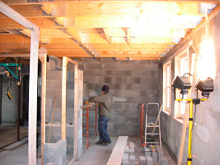
I have mentioned before about the choice of a suspended block and beam construction for the first floor, how solid it seems and how it provides a stable platform to work on, but it has it's downside, there's nothing to fix the plasterboard ceilings to!! A matrix of  timber was required across the whole of the ground floor ceiling, easy and quick to say, but time consuming to provide.

Timber Matrix fixed to beams

The matrix consists of 2x2 timber attached to the concrete beams with a steel bracket, bent over and secured with nails, then timber noggins at appropriate spacings fixed between. The brackets are only hooked over the beams and trapped under the blocks, is this going to hold up the weight of the ceiling?? Well its still up there!.


Another job to get done before plastering was to screed the floor. I did not expect to have to do this one because as we would be tiling or timbering(is that a real word?) the ground floor it would not be necessary for it to be perfectly smooth,  but the unfortunate circumstances at the beginning of the build ( see 'Getting on with it') rendered the floor like the ocean waves, so screeding it was.
A young chap just starting out on a new business adventure, popped his head in one day and offered to do the floor with a flowing gypsum based screed, the price seemed good, a quick job(one day) and a perfectly flat floor was the promise. It looked good and offered a great solution except that, it was twelve months later when I asked him to do it, he had established his business and the price had gone up. However it was a great job, another layer of insulation, dpm,and 40mm flowing screed and it was done. No one said to me that it would be necessary to scarify the finished surface in order for anything to stick to it though, more of that later!!


Polystyrene laid prior to DPM and screed


Kitchen floor showing completed screed. Lovely finish

The trouble with having bedrooms on two floors (amongst other things) is that at least 100mm worth of sound deadening insulation is required between floors. Not too bad a job I hear you say, until you consider how to hold it up there until the plasterboard is fixed. A lot of pondering then several bundles of string and a good stapling gun is what was required! plus loads of suitable insulation. (Wickes do bats of suitably stiff insulation, which we bought rather a lot of). It was a good game for a few days, my wife holding up the insulation whilst I stapled a criss-cross network of string to hold it in place. Job done!

Insulation between the joists held up with loads of string!

Of course there was quite a bit of first fix joinery to do before the plasterers arrived and that involved fixing door linings to all openings, constructing a false chimney over the planned kitchen range(see above picture), fixing the remaining stair spindles (although in hindsight this would have been better left until later) making false ceilings in the sun room to accommodate lighting(see below) and constructing false walls in the bathrooms to conceal the cisterns and piping.


Because the ceiling was sloping we had to provide false bits along the edges of the sun room to accommodate the lighting
I hate boxed in pipes! so I was determined that all pipework was made as discrete as possible and to this end we decided to conceal all the cisterns and soil pipes behind false walls in all the bathrooms and to have suspended basins and loos. This decision involved considerable timber framework strong enough to support a wall mounted loo with someone sitting on it!


I'm getting the cart before the horse here because in this picture the plastering is done, but you can see the framework provided for the false walls.


Substantial timber framing to provide false walls where cisterns, soil pipes and water pipes could be concealed and provide a cleaner look to the bathrooms.


Framework for Luxury Bath. Don't look much now but I assure you it will


We don't have much thievery around hear being a remote little village, but during this period I was aghast to one morning to wake up and find my Landrover had walked, off the driveway!! Security suddenly became an issue and as we stored much of our building materials in the garage we thought it high time we fitted the garage doors.


 Beautiful garage doors with well engineered Hormann Frames and Cedar cladding. 
Supplied by The Garage Door Company


I then had to find a new car and spend precious cash

I have only included here a few of the many jobs we did in preparation for plastering as they are too numerous and basic to mention so it's on with the next big step, plastering.


Plastering Supplies arrive courtesy of B&Q
A good price matching deal from B&Q provides all the materials required for the next job, but that's for next time on the 'The Real Self Build Blog'


If you have any questions about my blog or self build in general please email me. You can find my email address in my profile (top right of page). You can also become a follower of my blog by pressing the follower button or click on 'Comments' below to leave a message.  

Thanks for viewing.


Monday, 14 November 2011

Water Works

First fix electrics were in and it was time to do first fix for the plumbing. I have always enjoyed plumbing work, soldering joints etc there is something satisfying about cleaning up the ends of copper pipe, the inside of Yorkshire fittings, coating with flux and heating the joint so that the solder flows uniformly around the joint making a neat water proof seal, sad or what? Anyway I originally started off intending to do all the plumbing in copper but ease of use and cost soon put paid to that. Before long I was using plastic for all pipework where ever it was supported throughout its length.  Unsupported plastic pipe set into pipe clips looks awful where they are exposed and I suspect have the potential to fracture over time due to the drooping effect of the pipes as they expand with the heat. Although individual copper fittings are generally cheaper than plastic a joint of some kind is required at least every 3mtrs (standard length of copper pipe) so plastic tends to cost in over longer lengths. It is also easier to produce a watertight joint with plastic first time. So it was with these factors in mind that a mixture of copper and plastic was used throughout the house. 
   Providing hot and cold feeds to all sinks and baths is not particularly difficult but guidance can be sought with regard to the regulations from the the Water Regulations Advisory Service(WRAS) who will provide you with a copy of their booklet, a very descriptive and helpful guide.

First Pipework


Pipework in Place
   First fix cannot be completed without knowing what and where all the components of the system will be so a few decisions were required. Like all good self builders I like to be unconventional (hence block and beam for the first floor) so in true fashion I decided on a thermal store to provide hot water and space heating. Not the first choice for heating engineers and plumbers and probably due to their complex electronics, however there was good reason, 'I like a good shower'.  That means more than a trickle, so as the water pressure appeared to be very high in this area, (I had several burst hose pipes during building) the choice of thermal store was a good one as (similar to a combi boiler) it heats the mains water as it comes into the house. Hot water is fed direct to the taps and showers giving mains pressure at the head with the ability to supply large amounts of hot water and with two en suites and two bathrooms, boy do you need it?Gledhill Water Storage were the manufacturer of choice but unfortunately they have since stopped making them, a victim of the recession!!
   The choice of boiler was on recommendation from a local service engineer and as I presumed he knew more about it than myself we chose his recommended Grant boiler with the size determined by the accumulation of the radiator sizes plus a bit for good measure, all guidance which can be found online.
   Central Heating is something I have never designed or installed before but there's always a first time for everything. How big should a radiator be? How many radiators does a room need? Where should they be sited?How powerful should the boiler be? There are a lot of options and decisions to be made and no doubt everyone will arrive at a different solution but in my case using what experience I had and the use of the Internet I designed my own system. Its amazing how little heat output is required in a modern house with all its insulation. My previous 1970's house had radiators the length of some walls but using an online design aid which took into account heat loss through outer walls, loss through adjacent rooms, ceilings and floors all the radiators turned out to be very small, some equivalent to the output of a single bar electric fire. I checked the results several times!! Radiators I here you say! yes we fitted radiators throughout the house despite protestations from me the better half won the day on this option.  We used ACOVA column radiators on special offer from B&Q for the aesthetic effect.

After plastering this is the room that I


put this radiator in. Small ain't it


Since all the walls in the house were solid block work there was no stud work and modern construction methods involve small bore pipework in the stud walls, therefore I had to find other means to feed the pipework to radiators, taps and showers. 
    On the first floor there was a false floor of  2x2 timber battens and chipboard flooring so a cavity was formed under which pipes could be laid and as all basins and cisterns were wall hung or enclosed there was no problem concealing pipes behind false walls. However on the ground floor it was necessary to bury the pipes under the floor screed  and apart from underfloor heating it is no longer acceptable to bury the pipes in the screed, so they were encased in a separate corrugated flexible tube, readily available from Screwfix and placed in the insulation under the floor screed.


Of course all loo's have to have a soil pipe and again these were readily accommodated behind false walls in the bathrooms.

False walls in Bathrooms to accommodate pipework and concealed cisterns.


All the pipe work was in place ready for the more exciting bit, second fix, where radiators, sinks, baths, toilets, showers, boiler and thermal store were to be fitted, not much left then!! However next, just the small question of plastering, but lots of bits to do first in preparation, but that's for next time on 'therealselfbuildblog'

If you have any questions about my blog or self build in general please email me. You can find my email address in my profile (top right of page). You can also become a follower of my blog by pressing the follower button or click on 'Comments' below to leave a message.  

Thanks for viewing.


Saturday, 10 September 2011

First Fix Electrics

All the rooms were defined in block work and shortly we would be ready for plastering, however just a small matter of first fix for plumbing and electrics. 

Now I am one for having a go at most things DIY but for the novice a word of caution. Electricity can kill!  I have a background in electronics, a good understanding of the difference between Volts, Amps and Watts, I have studied Ohms law and my training in the telecommunications industry encourages me to use best practices in all things electrical. If I sound like I am talking gibberish then its best for you to leave this part of a build to the professionals, however if like me you have the knowledge to undertake some of this work then it is not beyond the self builder armed with a good guide book to do so, with the proviso that a qualified electrician carries out the final inspection and tests and connects to the mains supply. 

So armed with my Collins complete wiring and lighting guide in hand I set about installing the mains and lighting circuits. Unfortunately my wife did not find taking photos of bits of wire very interesting so I am a little short of pics for this post.

Anyway, in simple terms a ring main starts at the consumer unit and runs around the house passing in and out at each socket outlet and finally returning to the the consumer unit. In theory the number of sockets is unlimited but in practice a limit is placed on the number by the floor area that one ring main can supply and that is 100 sq mtrs also generally each floor needs it's own ring. That's how I came to provide four rings as there are three floors and the ground floor is greater than 100 sq mtrs. Lighting circuits are a different matter and in their simplest form start out from the consumer unit and run in a radial circuit out to the last light with the limit being the maximum wattage of 1200watts ie:- 12 x 100watt bulbs. With fancy lighting this limit is soon used up hence I ended up with six radial ccts excluding the garage. Cookers, storage heaters and immersion heaters which draw rather more current than either lighting or ring mains all require a dedicated radial feed from the consumer unit and much heavier cable. 


Running cables is a case of finding the best route through the house usually in the loft, in the floor space between floors, in studded walls or chasing them into solid walls. Because I am anal, I had to have a more sophisticated solution and that involved providing cable runways and risers, which were born out of my communications background. So all my cables rise (on a vertical runway)from the garage, through two floors to the loft and then across the loft on a cable runway to a riser where they would fall to the floor voids and start running around the house, dropping down walls to the various sockets. Large numbers of cables running alongside each other tend to develop some heat and and this was another of the reasons that I provided the runway to take the cables above the insulation rather than on or under it. Similarly where lighting cables drop to lights in the loft the cables where attached to battens fixed to the rafters above the insulation then dropping directly to the light fittings, in this way any heat generated by the cables easily escapes reducing any potential fire risk.

Typical Riser, this one in the Utility Room mainly for pipe work

A drawback to having solid internal walls is that all cable drops need to be chased in to the wall and protected and this turned out to be a very long and messy job. Best practice for cable drops dictate that they should be vertical ie:- no diagonal runs to save cable, however where sockets are reasonably adjacent to each other short horizontal runs are permissible. This  practice ensures reasonable confidence as to where cables are located after plastering and hopes to avoid fireworks with a wayward drill. Wall boxes of varying types were provided at the end of each drop and the punch out holes in the metal types protected with a rubber grommet. Cable tails (ready for second fix) at the wall box were left 150mm to 200mm long to help with termination later.

There are several fittings which require a spur off  the ring mains and these included extractor fans, auxiliary lights over bathroom mirrors and fixed appliances all of which require a fused outlet. Smoke detectors however must have a separate feed from the consumer unit and be linked to each other. The regulations with regard to bathrooms are very strict and need to be observed closely but in any case any electrician worth his salt will not pass any installation not up to the regulations, so I say again the system needs checking and testing by a qualified person before connecting to the mains. 


A loop of the ring main rises under the island unit. Kitchen ring shown running around at floor level no more than six inches from the floor is permissible.

Regulations and practices change so it is with some concern that I have written this post. I have not given specific details about providing mains electricity in a self build as it is not intended as a definitive guide and should not be taken as one, moreover reference should be made to a good guide and IEE regulations if necessary.

In the event fortunately for me, my installation passed testing and was duly connected to the supply by my friendly electrician without any problems or rework. There are many electricians out there quiet willing to undertake the commissioning of a domestic system like this as it is the more intellectual part of the job and removes much of the physical effort whilst still being profitable. It is also worth noting that a completion certificate issued by the electrician is required by the BCO before they will issue a completion certificate for any build.

That was all the cables in for the first fix, fitting of all the electrical goodies was to come after plastering. I now needed to get on with doing first fix for plumbing but first to design the central heating system. That's for next time on the 'realselfbuildblog'


If you have any questions about my blog or self build in general please email me. You can find my email address in my profile (top right of page). You can also become a follower of my blog by pressing the follower button or click on 'Comments' below to leave a message.  

Thanks for viewing.


Thursday, 14 July 2011

The next steps

After the milestone of installing the windows it was back to the less rewarding chore of more block laying. I know most modern houses have stud walls and the later ones are only very narrow so they appear very flimsy, but we were  determined to make ours look substantial so at the early stages we choose to use block work for all internal walls. It makes for a quality feel to a building but it needs the upper floors to be rigid and that's one of the reasons why we opted for block and beam upstairs. Laying the first few blocks on the upper floor started to show how the rooms fitted into the shell of the building and for the first time the internal layout started to appear.


Rooms start to appear
  Once we had finalised the boundaries for all the rooms the stairs could be fitted. We had previously ordered the stairs which consisted of one straight flight and a double flight with quarter landing from a local manufacturer called,  wait for it!  'The Timber Stair Manufacturers Ltd' original isn't it. However they were very good, their designer came to site to measure up and as I had never fitted a set of stairs before he was very helpful and gave me lots of guidance.
The kit of parts arrived soon after placing the order and were extremely good quality with Hemlock strings and spindles, Oak base rails and handrails and MDF treads. The solid oak option was prohibitive!!

Kit of parts arrive for the stairs

 Now to get them in place, a job for more than one man and his wife so the regulars popped over to help. Not to worry though the straight flight went in first and after constructing the framework for the quarter landing (not supplied) the flight was lifted into position. The newel posts and strings were already mortised and tenoned so it was just a case of gluing them together with the handrail, lifting into place and fixing the top newel post to the joists. It was almost like building with Lego, each part slotting together easily, the only bit of real joinery was cutting the handrails to length and cutting the tenons on the ends.        

The regulars on site to help install the stairs

Initial installation complete. Newel post bolted to trimmers between joists

 The other set of stairs was less simple, with a quarter landing half way up (not supplied) the framework for the landing had to levitate somewhere in the air. I decided the most solid means of achieving this was to build a tower of blocks in the corner on which to stand the frame and also create a useful cavity under the stairs accessed from the little room.

 
My wife thought this was funny
Initial installation of the lower stairs complete. The newel posts at the top were bolted to a steel beam which supports the landing. A very solid fix.

 That was the stairs in place so it was no longer necessary to climb ladders between floors, suddenly a flash of inspiration !!   Why not move into the loft? (temporarily you understand) just one problem, no insulation, so that was the next job.
I mentioned in an earlier post that we had designed the roof as a sealed roof and part of that design was that there should be an air space between the insulation and the roof membrane, so it was now necessary to provide the insulation and maintain that space.
The 100mm polyisocyanurate(I hate that word) needed to fit between all the rafters in the loft and should be cut to a snug fit and pressed into place without going in too far and compromising the air space. To prevent this, battens were fixed to every face of all the rafters 100mm in from the underside.
Fitting the insulation by cutting with a standard timber saw must be the most messiest and  uncomfortable job I have done to date. The cutting generates clouds of choking particles which stick too your clothes with static, and spread everywhere. A second layer of 30mm insulation had to be fitted over the first to meet building regulations and this was fixed with screws and washers but thankfully in the last minute before fitting this layer which covered the rafters we remembered to mark the floor with their position or the plasterers would have cursed us.  A few days later we had an insulated loft.


Insulation ready for installation, lot of it isn't there
In Progress
First layer finished

 Just a lick of paint and building the only stud wall with a cheap door in it and we moved in!!


Bed from the caravan
Must have a tele
Xtratherm, Xtratherm, Xtratherm dreams are made of this.


 Home from Home! It was good to get out of the caravan,  a couple of winters did the trick but we still had to cook in there.


Insulating the kitchen and garden room ceiling

More insulation, phew!! its getting warm in here


Well that's it for now but next time on 'therealselfbuildblog' I will tell you how we started the plumbing and electrics and prepared for plastering.

If you have any questions about my blog or self build in general please email me. You can find my email address in my profile (top right of page). You can also become a follower of my blog by pressing the follower button or click on 'Comments' below to leave a message.  

Thanks for viewing.


Monday, 4 July 2011

Icing on the cake

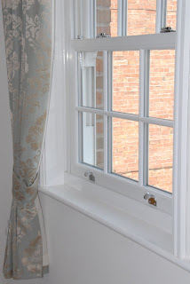
Here we are, complete shell, all bricks layed, roof on and fiddly bits done, now for the finishing touches, the beautiful Sash Windows. We had right from the early days of planning and design decided on Sash windows as the house that we had admired and used as our template  had sash windows, albeit in timber. Ours were to be uPVC   Urgh!!  I here you all say,  however consider this, we have twenty three Georgian style windows in white, think of all that painting every five years or so, it would be like painting the Forth Bridge and anyway the quality windows we have chosen are almost indistinguishable from timber and a lot less prone to rot.

Like yourselves, in the beginning, we were avid readers of anything we could get our hands on to do with self build and it was as we scoured the pages of Homebuilding and Renovating Magazine that we first came across the name of GlynGary Windows. A small family run business, hence the name Glyn and Gary, which specialises in the construction of uPVC AND Timber Sash Windows and who are based in Warrington. Inspired by the advertisements we called them and were duly invited to visit the factory. 

They have a great set up and showed us many of their products and although they do not fit windows  many them are fitted in the likes of Government buildings in London. It was the father of the two boys who first suggested fitting our windows behind the brickwork opening instead of in the  opening as is the modern practice. This method adds to the character of the both the window and the building, reduces the profile of the window frame that can be seen and with the overhang of the bricks provides some additional protection for the windows, less cleaning!!  

Here you can see one of the windows set behind the brickwork. Very Georgian.
A method of fixing was required and as much of the frame spans the cavity, fixing through the frame into the wall was difficult. Another GG suggestion was to use an additional timber frame as used  in the Georgian era  and therefore provide timber reveals with Torus profile architrave to match, very much in keeping with the style of the house. I hasten to add that the timber does not span the cavity as this would cause damp problems.
One of the windows(at a much later stage obviously) showing the timber reveals and architraves
We ordered our windows from GlynGary at very reasonable cost and the day dawned shortly after when they arrived and our second team were there to help with the offloading.


Meanwhile the scaffolding had been removed to reveal the house and it was with much excitement that we started to fit the first windows.

A cavernous space in which to construct the frames for the windows

The first of many frames finished and waiting for a liberal coating of preservative

First one in

From the outside

All windows in, even got the garden room roof on in this one

In at the front too
Well that was it, brickwork done, roof on, windows in, we can move in next week,   Nah!!   My friendly local builders chance remark was 
'it's reckoned that when the shell is up your just about half way there', encouraging eh!!

Next time on the therealselfbuildblog I'll tell you how we progressed to the inside and moved in, although in a temporary fashion.
 
If you have any questions about my blog or self build in general please email me. You can find my email address in my profile (top right of page). You can also become a follower of my blog by pressing the follower button or click on 'Comments' below to leave a message.  

Thanks for viewing.


Sunday, 26 June 2011

On with the roof, Part 2

 Although the joiner guys I employed had fixed all the trusses they were unable to finish the trusses around the openings for the roof lights. That was left to me!!!

Here I am fixing the remaining roof members around the roof lights

Never having built a roof before I needed to take some guidance on the next steps. Most of my skills have been developed by employing the techniques learned from considerable reading and dedicated observation of the professionals as well as lots of practice over the many years that I have been doing construction jobs, both at home and for other people. This job was to be no exception and the one really useful piece of  literature that I used to construct the roof was Kingspans guide to insulated roofs. A small booklet which lists the different types of roofing construction methods involving tiles, tile battens and roof membranes. Being the person I am I chose to follow the most involved method of construction which does  produce the most thermally efficient roof but is also the most complex, that method is called in their booklet a 'sealed roof' ie:- sealed all around the edges and between the different courses of membrane so that there is no path between the outside air and the air under the membrane. Normally accepted methods involve draping the membrane between rafters and not sealing between the subsequent layers whereas my chosen route demands a taut membrane and the sealing between layers which presents some difficulties and non-standard methods of construction, of course!!
Because the membrane is taut the tile battens cannot be fixed directly to the rafters as there is no way for any water to drain so counter battens are required. (see pictures) A further difficulty was how do I  access the second and subsequent courses of membranes to remove the release film between layers.

Preparing the valleys


The Tyvec membrane used here is non regular 1.5m width with adhesive seal.
Well the solution was to cut the counter battens to just short of the width of the membrane and fix the lower tile battens first to provide a ladder to access the next layer, simple!!

Working up the roof fixing battens to form a ladder to fix the next membrane course
Working out the solution to the next problem caused some head scratching. Of course the professionals out there will work this one out in their sleep, "spacing of the battens", One roof with two sides may be fairly simple, fix the top and bottom batten, measure between and divide by the number of courses of tiles taking into account minimum cover, however in this case I had two roofs, both with the same pitch but of different base width and different heights and I wanted to keep the courses in line with each other, so one optimum spacing was not necessarily OK for the other roof, a compromise was needed ? Some measuring, puzzling, swearing, mumbling and a few guesses later a compromise measurement was decided on, so now we could fix the battens.
A little trick I used here to maintain the spacing between battens was to cut several pieces of timber to the requisite length and use them between battens whilst fixing them. I am probably not the first to think of that one??
All the battens in line,very neat
 
Getting towards the ridge with the battens. Note the vacant area for the roof lights

Fixing the leading in the valleys. Another tricky job!

There are nine roof lights in this build so by the time I get to the last I should have got it sussed!! Not that difficult really, Velux have got it well engineered here, very well made with complete instructions but it was still with trepidation that I  put the first knife cut in the membrane. Should not have worried though and managed to fix four in a short space of time and I was ready for the first tiles.

You don't cut through a membrane like that without some worry.

Well that wasn't too bad
The tiles were next and I was determined that the roof should look professional although having said that I have seen some awful professional jobs,wiggly courses both up and across, uneven courses and cut verges. In order to avoid these obvious defects spacing of the tiles was critical (and difficult) and I used a builders line top to bottom to ensure the tiles were in line.
It was a small remark by my NHBC inspector but one that increased the amount of work dramatically, 'Get hold of a nailing pattern from the tile manufacturer' he said glibly. I did and in my area it required that all tiles should be nailed, with tile clips on two courses of tiles around all openings, eaves, ridges and verges and tile retaining straps on all verges. what!!!! you would think we lived in the wilds of Scotland and not the East Midlands but we had to comply to get our Solo certificate.

The first tile to go on and verge clips for every course of tiles


Our regular volunteer helpers


The completed front roof without roof lights, hopefully it looks as neat to you as it does me. The back roof with lights is not quite as I would like it due to the constraints of spacing around the roof lights themselves but it is more than acceptable.
Well just the small job of mortaring the verges, fixing the ridge tiles, leading around the chimney and fixing the beautiful Brett Martin cast iron effect rain ware and the roof is complete. Just like that!!

Next time on 'The Real Self Build Blog' I will tell you about the beautiful GlynnGary sash windows and how we fitted them.

If you have any questions about my blog or self build in general please email me. You can find my email address in my profile (top right of page). You can also become a follower of my blog by pressing the follower button or click on 'Comments' below to leave a message.  

Thanks for viewing.